Computer Organization and Structure
Homework
#5
Due:
2007/12/25
1. Consider
the single-cycle datapath in Figure 1. A friend is
proposing to modify this single-cycle datapath by eliminating the control
signal MemtoReg. The multiplexor that has MemtoReg as an input will instead use
either the ALUSrc or the MemRead control signal. Will your friend’s
modification work? Can one of the two signals (MemRead and ALUSrc) substitute
for the other? Explain. Furthermore, determine whether any of the control
signals in the single-cycle implementation can be eliminated and replaced by
another existing control signal, or its inverse. Note that such redundancy is
there because we have a very small set of instructions at this point, and it
will disappear (or be harder to find) when we implement a larger number of
instructions.
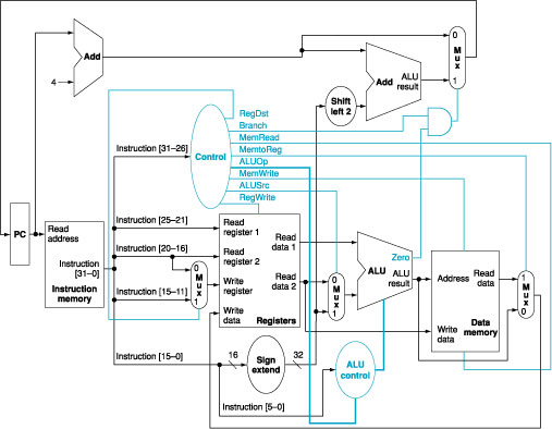
Figure
1: The simple datapath with the
control unit.
2. We
wish to add the instructions jr
(jump register), sll
(shift left logical), lui
(load upper immediate), and a variant of the lw (load word) instruction to
the single-cycle datapath. The variant of the lw instruction increments the index register after
loading word from memory. This instruction (l_inc) corresponds to the following two instructions:
lw $rs, L($rt)
addi $rt,
$rt, 1
Add
any necessary datapaths and control signals to Figure 1 and show the
necessary additions to Table 1. You can
photocopy Figure 1 and Table 1 to make it
faster to show the additions.
|
Instruction |
RegDst |
ALUSrc |
Memto |
Reg |
Mem |
Mem |
Branch |
ALUOp1 |
ALUOp0 |
|
R-format |
1 |
0 |
0 |
1 |
0 |
0 |
0 |
1 |
0 |
|
lw |
0 |
1 |
1 |
1 |
1 |
0 |
0 |
0 |
0 |
|
sw |
X |
1 |
X |
0 |
0 |
1 |
0 |
0 |
0 |
|
beq |
X |
0 |
X |
0 |
0 |
0 |
1 |
0 |
1 |
Table
1: The setting of the control
lines is completely determined by the opcode fields of the instruction.
3. Two
important parameters control the performance of a processor: cycle time and
cycles per instruction. There is an enduring trade-off between these two
parameters in the design process of microprocessors. While some designers prefer
to increase the processor frequency at the expense of large CPI, other
designers follow a different school of thought in which reducing the CPI comes
at the expense of lower processor frequency. Consider the following machines,
and compare their performance using the following instruction mix: 25% loads,
13% stores, 47% ALU instructions, and 15% branches/jumps.
M1:
The multicycle datapath is designed as shown in Figure 3 with a 1 GHz
clock.
M2: A
machine like M1 except that register updates are done in the same clock cycle
as a memory read of ALU operation. Thus in Figure 4, states 6 and 7
and states 3 and 4 are combined. This machine has an 3.2 GHz clock, since the
register update increases the length of the critical path.
M3: A
machine like M2 except that effective address calculations are done in the same
clock cycle as a memory access. Thus states 2, 3, and 4 can be combined, as can
2 and 5, as well as 6 and 7. This machine has a 2.8 GHz clock because of the
long cycle created by combining address calculation and memory access.
Find
out which of the machines is fastest. Are there instruction mixes that would
make another machine faster, and if so, what are they?
Figure
2: The multicycle datapath with
the control lines.
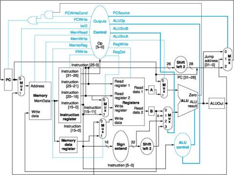
Figure
3: The complete datapath for the
multicycle implementation together with the necessary control lines.
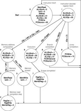
Figure
4: The complete finite state
machine control for the datapath shown in Figure 2.